OSCAR Platform
Platform for network compatible industrial equipment with Intel MAX 10 FPGA

OSCAR plarform is developed mainly for IoT network devices.
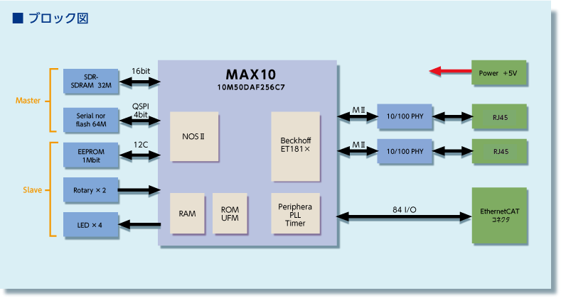
- With MAX10 10M50 mounted: Single-chip custom CPU can be implemented by using NiosII, since it is possible to use FLASH that can be concurrently used as RAM with sufficient capacity and Configuration ROM.
- With External SDRAM, QSPI Flash: Can be expanded in accordance with the software application size.
- Since two 10/100 PHYs are mounted in the FPGA, network-enabled devices can be easily implemented by using TSE MAC from Intel Corporation etc.


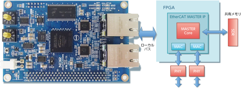
EtherCAT Implementation
- Hardware Master
It is possible to evaluate our hardware master.
It is developed as an “instant EtherCAT” in retrofit to existing CPU boards. - Slave
Ethernet of the FPGA can also be used as a slave by implementing BECKHOFF EtherCAT slave IP etc.


Specifications
| Core specifications | ||
|---|---|---|
| FPGA | MAX10 Series | 10M50DAF256C7G |
| Dual configuration compatible: Config data select in SW4 | ||
| Power supply | Input: 5.0V | Supplied from power Connector (B2P-VH) or extension connector |
| Output: 3.3V | 3.3V output from extension connector (assumed to be used as a power supply for tolerant buffer) | |
| Clock | 25MHz | 1 unit mounted |
| GPIO | 2 No.s of 1.27 25x4 rows of staggered connectors | FX2C - 100 S - 1.27 DSA (Hirose Electric) |
| CN4: FPGA part 81CH | ||
| Ethernet | 100base Ethernet (2CH): FPGA | CN2, CN3 PHY: TLK110PTR |
| LED | POWER LED | 1 unit (green) |
| USER LED | 2 units (green) | |
| EtherCAT LED | RUN (1 green), ERR1 (1 Red) | |
| Rotary switch | 2 decimal units | Connected via buffer and can connect any one to gate control (SW1, SW2) |
| Push switch | 1 unit | Reset switch (SW3) |
| JTAG | Connector | 1 unit (CN1) |
| Memory | SDRM | 32MByte 1 unit (x16bit) MAX 167MHz |
| QSPI flash | 521Mbit (64Mx8bit): MT25QL512ABB8E12-0SIT | |
